Electromagnetic Methods
Electromagnetic Induction Process
The electromagnetic induction process is conceptually summarized in figure 1 from Klein and Lajoie (1980). An EM transmitter outputs a time-varying electric current into a transmitter coil. The current in the transmitter coil generates a magnetic field of the same frequency and phase. Lines of force of this magnetic field penetrate the earth and may penetrate a conductive body. When this occurs, an electromotive force or voltage is set up within the conductor, according to Faraday's Law:
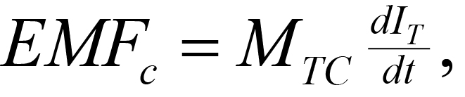 (1)
(1)
where
EMFC = electromotive force or voltage in the conductor,
MTC = mutual inductance between the transmitter and the conductive body in the ground (a complex number),
dIT/dt = time rate of change (derivative) of the current (IT ) in the transmitter loop.
Current will flow in the conductor in response to the induced electromotive force. These currents will usually flow through the conductor in planes perpendicular to lines of magnetic field of force from the transmitter, unless restricted by the conductor's geometry. Current flow within the conductor generates a secondary magnetic field whose lines of force, at the conductor, are such that they oppose those of the primary magnetic field. The receiver coil, at some distance from the transmitter coil, is therefore energized by two fields: from the transmitter and from the induced currents in the ground.
Figure 1. Generalized picture of electromagnetic induction prospecting. (Klein and Lajoie 1980; copyright permission granted by Northwest Mining Association and Klein)
From Faraday's Law, the EMF induced in the receiver may be expressed as
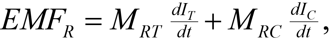 (2)
(2)
where
EMFR = EMF induced in the receiver,
MRT = mutual inductance between the receiver (R) and transmitter (T)
MRC = mutual inductance between the receiver (R) and conductor (C) in the ground, a complex number,
dIC/dt or dIT/dt = time derivative of the current induced in the conductor (C) or transmitter (T),
IT or IC = current induced in the conductor (C) or transmitter (T).
Note that induced currents occur throughout the subsurface, and
that the magnitude and distribution are functions of the
transmitter frequency, power, and geometry and the distribution of
all "electrical properties" in the subsurface, i.e., everything
(not just an isolated "conductor"). The above discussion
simplifies the problem by assuming the presence of only one
conductor embedded in a much less conducting medium.
The pages found under Surface Methods and Borehole Methods are substantially based on a report produced by the United States Department of Transportation:
Wightman, W. E., Jalinoos, F., Sirles, P., and Hanna, K. (2003). "Application of Geophysical Methods to Highway Related Problems." Federal Highway Administration, Central Federal Lands Highway Division, Lakewood, CO, Publication No. FHWA-IF-04-021, September 2003. http://www.cflhd.gov/resources/agm/![]()