Very Low-Frequency (VLF) Method
Basic Concept
The VLF method uses powerful remote radio transmitters set up in different parts of the world for military communications (Klein and Lajoie, 1980). In radio communications terminology, VLF means very low frequency, about 15 to 25 kHz. Relative to frequencies generally used in geophysical exploration, these are actually very high frequencies. The radiated field from a remote VLF transmitter, propagating over a uniform or horizontally layered earth and measured on the earth's surface, consists of a vertical electric field component and a horizontal magnetic field component each perpendicular to the direction of propagation.
These radio transmitters are very powerful and induce electric currents in conductive bodies thousands of kilometers away. Under normal conditions, the fields produced are relatively uniform in the far field at a large distance (hundreds of kilometers) from the transmitters. The induced currents produce secondary magnetic fields that can be detected at the surface through deviation of the normal radiated field.
The VLF method uses relatively simple instruments and can be a useful reconnaissance tool. Potential targets include tabular conductors in a resistive host rock such as faults in limestone or igneous terrain. The depth of exploration is limited to about 60% to 70% of the skin depth of the surrounding rock or soil. Therefore, the high frequency of the VLF transmitters means that in more conductive environments, the exploration depth is quite shallow; for example, the depth of exploration might be 10 to 12 m in 25-Ωm material. Additionally, the presence of conductive overburden seriously suppresses response from basement conductors, and relatively small variations in overburden conductivity or thickness can themselves generate significant VLF anomalies. For this reason, VLF is more effective in areas where the host rock is resistive and the overburden is thin.
Case Histories
VLF response is a maximum when the target strikes in the direction of the transmitter, falling off roughly as the cosine of the strike angle for other directions. However, there are a number of transmitters worldwide and seldom is the selection of an appropriate transmitter a problem. Because of the rudimentary nature of VLF measurements, simple interpretational techniques suffice for most practical purposes. The conductor is located horizontally at the inflection point marking the crossover from positive tilt to negative tilt and the maximum in field strength. A rule-of-thumb depth estimate can be made from the distance between the positive and negative peaks in the tilt angle profile.
One cannot make reliable estimates of conductor quality, however. Finally, the major disadvantage of the VLF method is that the high frequency results in a multitude of anomalies from unwanted sources such as swamp edges, creeks, and topographic highs. A VLF receiver measures the field tilt and hence the tilt profile shown in figure 1 (Klein and Lajoie, 1980). Figure 1 also shows schematically how the secondary field from the conductor is added to the primary field vector so that the resultant field is tilted up on one side of the conductor and down on the other side. Some receivers measure other parameters such as the relative amplitude of the total field or any component and the phase between any two components. Figure 2 (Klein and Lajoie, 1980) shows a comparison of the main types of measurements made with different VLF receivers. A variant of VLF measures the electric field with a pair of electrodes simultaneously with the tilt measurement.
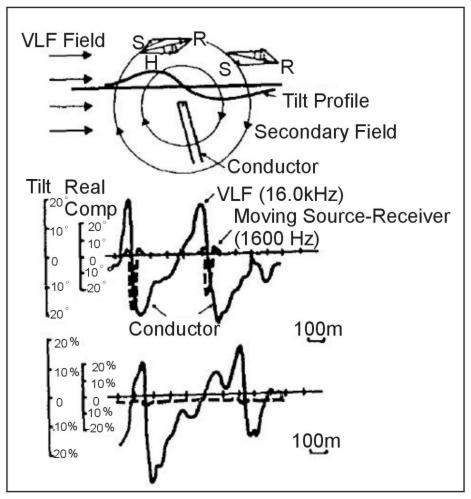
Figure 1. Tilt of the VLF field vector over a conductor. (Klein and Lajoie, 1980; copyright permission granted by Northwest Mining Association and Klein)
Case History
Groundwater. Figure 3 presents VLF results taken over granite terrain in Burkina Faso, Africa (Wright, 1988, after Palacky, Ritsema, and De Jong, 1981). The objective of the survey was to locate depressions in the granite bedrock, which could serve as catchments for groundwater. Depressions in the very resistive bedrock beneath poorly conductive overburden (100 to 300 Ωm at this site) likely produce VLF responses as a result of galvanic current flow. That is, the large current sheet flowing in the overburden, as a result of the primary electric field, is channeled along these bedrock depressions and appears as a line of anomalous current. The conductor axis is centered near station 70 to 75. A water well was drilled at station 70 and encountered bedrock beneath approximately 20 m of overburden and flowed at a rate of 1.0 m3/hour.
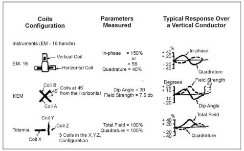
Figure 2. Comparison of VLF instruments. (Klein and Lajoie, 1980; copyright permission granted by Northwest Mining Association and Klein)
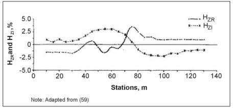
Figure 3. VLF profile, Burkina Faso, Africa. (Wright, 1988; copyright permission granted by Scintrex)
Buried Cables. Figure 4 presents VLF measurements along a profile crossing a buried telephone line (Wright, 1988). A classic crossover is observed that places the line beneath station -2.5. However, this curve is a good example of a poorly sampled response, because the exact peaks on the profile are probably not determined. One possible model is presented on figure 4 for a line current at a depth of 1.25 m and station -2.5. The fit is only fair, which could be the result of poor station control, inapplicability of the line current model, or distortion of the measured profile by adjacent responses.
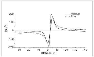
Figure 4. VLF profile over buried telephone line. (Wright, 1988;copyright permission granted by Scintrex)
The pages found under Surface Methods and Borehole Methods are substantially based on a report produced by the United States Department of Transportation:
Wightman, W. E., Jalinoos, F., Sirles, P., and Hanna, K. (2003). "Application of Geophysical Methods to Highway Related Problems." Federal Highway Administration, Central Federal Lands Highway Division, Lakewood, CO, Publication No. FHWA-IF-04-021, September 2003. http://www.cflhd.gov/resources/agm/![]()