Seismoelectrical Method
Basic Concept
The Seismoelectrical method (also called the Electroseismic method) is based on the generation of electromagnetic fields in soils and rocks by seismic waves. Although the method is not reported to detect groundwater flow, it does measure the hydraulic conductivity, which is related to permeability and, therefore, to the potential for groundwater flow.
The phenomenon is illustrated by figures 1 and 2.
When a seismic wave encounters an interface, it creates a ge separation at the interface forming an electrical dipole. This dipole radiates an electromagnetic wave that can be detected by antennae on the ground surface.
As in the case shown in figure 1, an antenna on the ground surface is used to detect the electric field. In the case illustrated in figure 2, a seismic head wave traveling along an interface creates a ge separation across the interface, which induces an electric field.
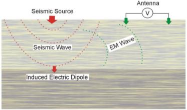
Figure 1. Seismoelectrical conversion at an interface.
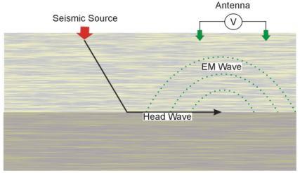
Figure 2. Generation of an electric field by a head wave.
As the seismic (P or compression) waves stress earth materials, four geophysical phenomenon occur:
1. The resistivity of the earth materials is modulated by the seismic wave;
2. Electrokinetic effects analogous to streaming potentials are created by the seismic wave;
3. Piezoelectric effects are created by the seismic wave; and
4. High-frequency, audio- and high-frequency radio frequency impulsive responses are generated in sulfide minerals (sometimes referred to as RPE).
The dominant application of the electroseismic method is to measure the electrokinetic effect or streaming potential (item 2, above). Electrokinetic effects are initiated by sound waves (typically P-waves) passing through a porous rock inducing relative motion of the rock matrix and fluid. Motion of the ionic fluid through the capillaries in the rock occurs with cations (or less commonly, anions) preferentially adhering to the capillary walls, so that applied pressure and resulting fluid flow relative to the rock matrix produces an electric dipole. In a non-homogeneous formation, the seismic wave generates an oscillating flow of fluid and a corresponding oscillating electrical and EM field. The resulting EM wave can be detected by electrode pairs placed on the ground surface.
Surface seismic sources and measurement electrode pairs are generally used to measure the electrokinetic effect. Borehole systems also have been recently developed. A hammer blow or small explosive (black powder ge) are typically used for the seismic source. Two, short (few meters) electrode pairs are typically located collinear and symmetric to the seismic source. Stacking of repeat seismic "shots" is often used to improve signal to noise.
The only company found that produces a commercially available electroseismic prospecting system is GroundFlow Ltd. in the UK. This system has been mainly used for field demonstration purposes and research and development studies. Very few detailed case histories are available to web manual the performance of the system. The electroseismic system made by GroundFlow is called "GroundFlow 1500" and the main equipment components are:
1. A combined computer-receiver
2. Antenna cables and electrodes,
3. Trigger cable
The Groundflow 1500 instrument is shown in figure 3.
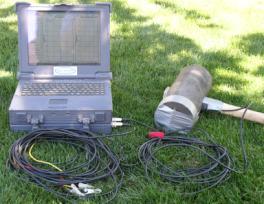
Figure 3. Ground Flow 1500 instrument. (Groundflow Ltd.)
The computer-receiver contains a preamplifier, analog to digital converter and power supply system to measure the voltages induced in the grounded dipoles. One system layout used to measure the electroseismic effect is shown in figure 4.
The hammer and plate seismic source is used along with two pairs of electrodes arranged in a straight line with electrodes offset (from the center of the array) by 0.25 and 2.25 m. The seismic source is positioned in the center of the array. Larger electrode spacing can be used; however, they are typically centered in pairs around the shot point and are generally less than about 10 m in length. Timing of the measurement is achieved by a hammer trigger (or other mechanical trigger). The signal is acquired with the instrument shown in figure 3. Measurements are made for a period of 400 ms after triggering. The last 200 ms of the record is used as a sample of background noise and is subtracted from the first 200 ms of signal in order to remove the first, third, and fifth harmonics of the background noise at the receivers. This noise is typically from power lines.
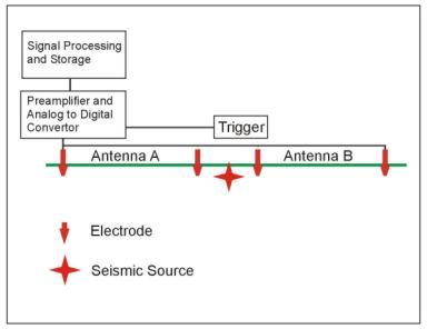
Figure 4. System layout for electroseismic surveys.
Data Acquisition, Processing, and Interpretation
Measurements are recorded using the instrument and system setup described above. Data processing consists of stacking repetitive hammer (or explosive) shots and removal of power line and other noise as described above. This processing is conducted on the computer-receiver while in the field. Depending upon field conditions, up to 20 soundings can be conducted in a day. It is expected that measurement time will increase proportionally with stacking times, and that long stacking times would be needed in the vicinity of power lines.
The signal files are processed to give a sounding plot of permeability and porosity against one-way seismic travel time. Values for a simple seismic velocity model are required to allow time- to-depth conversion. The resulting logs against depth are displayed in the field.
Output from the electroseismic inversion is typically a plot showing hydraulic conductivity versus depth. This interpretation assumes a one-dimensional layered earth. In theory, the inversion also can derive fluid conductivity and fluid viscosity from the rise time of the signal. Where many soundings are measured in close vicinity, a pseudo 2-D cross section can be generated.
The maximum depth of penetration of electroseismic measurements is stated to be about 500 m depending upon ambient noise and water content. Lateral resolution is not stated in the literature but is expected to be on the order of the depth of exploration. No information was found regarding the vertical resolution of the method.
Limitations
The electroseismic method is apparently susceptible to electrical noise from nearby power lines. Typical electroseismic signals are at the microvolt level. The electroseismic signal is proportional to the pressure of the seismic wave. Thus, it would seem possible to increase the signal by using stronger seismic sources. This is not mentioned in the literature. Electroseismic soundings have a maximum exploration depth of about 500 m in the reported literature, although no examples have been shown with results from deeper that about 150 m.
The pages found under Surface Methods and Borehole Methods are substantially based on a report produced by the United States Department of Transportation:
Wightman, W. E., Jalinoos, F., Sirles, P., and Hanna, K. (2003). "Application of Geophysical Methods to Highway Related Problems." Federal Highway Administration, Central Federal Lands Highway Division, Lakewood, CO, Publication No. FHWA-IF-04-021, September 2003. http://www.cflhd.gov/resources/agm/![]()