Flow Logging
Basic Concept
The measurement of flow within and between wells is one of the most useful well-logging methods available to interpret the movement of groundwater and contaminants. Flow measurement with logging probes includes mechanical methods, such as impellers, chemical and radioactive tracer methods, and thermal methods (Crowder, Paillet, and Hess, 1994). Their primary application is to measure vertical flow within a single well, but lateral flow through a single well or flow between wells also may be recorded by borehole‑geophysical methods.
The most common logging probe used at the present time for measuring vertical fluid movement in water wells is the impeller flowmeter, which is a relatively inexpensive and reliable instrument. Most impeller flowmeters incorporate a lightweight three- or four‑bladed impeller that rotates a magnet mounted on the same shaft. The magnet actuates a sealed microswitch, so that one or more pulses are impressed on low-voltage direct current that is connected across the switch. The impeller is protected from damage by a basket or housing, and the probe is centralized with bow springs, or similar devices, for best results. Baskets and impellers of different diameters are available and are easily changed, so the maximum size for a well can be used to increase sensitivity. Continuous logs of flow rate may be made at a constant logging speed and supplemented by more accurate stationary measurements at selected depths. The main shortcoming of impeller-type flowmeters is the lack of sensitivity to low-velocity flow. The most commonly used impeller flowmeters usually stall at vertical velocities of 1.2 to 1.5 m/min, although it is possible to measure velocities as low as one-half those velocities under some conditions. The addition of a packer or other flange-like device to divert most of the flow through the basket will improve sensitivity to low velocity, particularly in large-diameter wells.
Tracer Techniques
Tracer methods have been used in groundwater for many years, but only those that employ logging equipment are described here. Tracer techniques are useful at much lower velocities than impeller flowmeters; rates of about 1 m/day may be detected. The most commonly employed methods use a probe to follow the vertical movement of a chemical or radioactive tracer injected at selected depths in a well. An extension of this method may permit the detection of arrival of the tracer by logging adjacent wells. Radioactive tracers can be detected at lower concentrations than chemical tracers; most of them can be detected through casing. The difficulties in obtaining the permits necessary for using radioactive tracers have restricted their application. Temperature and fluid conductivity logs can also be used to measure flow rates between wells.
lA heat-pulse flowmeter originally was developed in England (Dudgeon, Green, and Smedmor, 1975). Its design was modified extensively, and a new probe was built by A. E. Hess of the U.S. Geological Survey (Hess, 1982). The modified version works reliably and has been used in wells to measure very low velocities. The logging system is shown schematically in figure 1, modified from Hess (1982). The wire heat grid, located between two thermistors, is heated by a 1-ms pulse of electric current, which is triggered from the surface. The heated sheet of water moves toward one of the thermistors under the influence of the vertical component of flow in the well. The arrival of the heat pulse is plotted on a t recorder running on time drive, as illustrated in figure 2. A deflection of the recorder trace to the right indicates upward flow, and to the left, downward flow. The system is calibrated in flow columns of various sizes for flow in each direction, because the tendency for heated water to rise and the asymmetry of the probe produce slightly different calibration curves in the two directions. The USGS heat-pulse flowmeter can be used to measure vertical water velocities from 30 mm/min or less to 12 m/min or greater, and it has advantages over both impeller flowmeters and tracer logging. An inflatable packer or flexible diverter can be attached to a flowmeter to force all flow through the probe and, thus, improve the performance of the heat-pulse flowmeter. A similar heat pulse flowmeter is now available commercially. A number of techniques have been tried for measuring horizontal flow in wells without much success or wide use. The technique may not provide an accurate estimate of average direction and velocity of flow in the aquifer because of the perturbations in the flow system caused by the well. A heat-pulse logging system has been developed for measuring horizontal flow (Kerfoot, 1982); it employs a series of paired thermistors located circumferentially around a heat emitter, and it is based on thermal transmission through an enclosing porous matrix of glass beads.
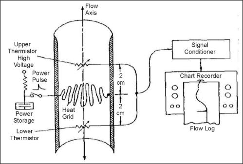
Figure 1. Equipment for making heat pulse flow meter logs. (Hess, 1982)
Normal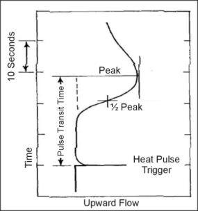
Figure 2. Analog record of a heat pulse from a thermal flowmeter. (Hess, 1982)
Data Acquisition
Calibration. Calibration of flow-measuring probes is done best in laboratory facilities designed for this purpose. Subsequent calibration checks and standardization may be carried out in a well under the proper conditions. The U.S. Geological Survey has designed and built a facility that is used for calibrating their flow‑measuring probes (Hess, 1982). The test facility consists of clear plastic columns with inside diameters of 5, 10 and 15 cm (2, 4, and 6 in) connected to a pump that can circulate water in either direction at velocities from 21 mm/min to 15 m/min, depending on column size. Onsite standardization or calibration can be performed by moving the flowmeter up or down a cased portion of a well at carefully controlled logging speeds. Calibration by this method is only valid at the casing diameter logged. An example of this type of calibration is shown in figure 3, where the pulses per unit time are plotted against the logging speed. The two lines with different slopes represent opposite directions of impeller rotation. The range of tool speeds near this intersection represents the stall zone where the velocity is too low to turn the impeller. Theoretically, this intersection represents the velocity at which water was flowing up the well.
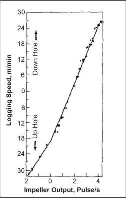
Figure 3. Calibration data for an impeller flowmeter.
The pages found under Surface Methods and Borehole Methods are substantially based on a report produced by the United States Department of Transportation:
Wightman, W. E., Jalinoos, F., Sirles, P., and Hanna, K. (2003). "Application of Geophysical Methods to Highway Related Problems." Federal Highway Administration, Central Federal Lands Highway Division, Lakewood, CO, Publication No. FHWA-IF-04-021, September 2003. http://www.cflhd.gov/resources/agm/![]()
.