Equipotential and Mise-a-la-Masse Methods
Basic Concept
According to Parasnis (1973), the equipotential method was one of the first electrical methods and was used as far back as 1912 by Schlumberger. As explained elsewhere in this volume, when electric energy is applied to two points at the ground surface, an electric current will flow between them because of their difference in electrical potential. If the medium between the two electrodes is homogeneous, the current and potential distribution is regular and may be calculated. When good or poor conductors are imbedded in this homogeneous medium, a distortion of the electrical field occurs. Good conductors have a tendency to attract the current lines toward them, whereas poor conductors force current flow away. Theoretically, it should be possible to detect bodies of different conductivity by measuring the geometric pattern of these current lines. In practice, this cannot be done with sufficient accuracy; it is necessary to determine the direction in which no current flows by locating points that have no potential difference (Heiland, 1940). The lines of identical electrical potential, called equipotential lines, are at right angles to the current lines. The equipotentials are circles in the immediate vicinity of the electrodes.
In the past, equipotentials were traced individually in the field by using a null galvanometer, but such a procedure was tedious and time-consuming. The modern practice is to measure the electric voltage at each observation point with respect to a fixed point, plot the results, and draw contours. The equipotential method was used extensively in the early days of geophysics, but has been almost completely replaced by modern resistivity and electromagnetic methods. When the method is used, it is usually in a reconnaissance mode, and quantitative interpretation of equipotential surveys is rarely attempted.
Mise-a-la-masse
One variant of the method, called mise-a-la-masse, is still used in mining exploration and occasionally in geotechnical applications. The name, which may be translated as "excitation of the mass," describes an electrode array, which uses the conductive mass under investigation as one of the current electrodes. In mining, the conductive mass is a mineral body exposed in a pit or drill hole. In geotechnical applications, the object under investigation might be one end of an abandoned metal waste pipe. The second current electrode is placed a large distance away. "Large" usually means five or ten times the size of the mass being investigated. The potential distribution from these two current electrodes will, to some extent, reflect the geometry of the conductive mass and would be expected to yield some information concerning the shape and extent of the body. The left-hand part of figure 1 (Parasnis, 1973) shows the equipotentials around a subsurface point electrode in a homogeneous isotropic earth. The right-hand part shows (schematically) the distribution of potentials such as might be expected when the point current electrode is placed in a conducting body situated in an otherwise homogeneous earth of lesser conductivity. In this case, the equipotentials tend to follow the ore body, and on the ground surface, the centroid of the equipotential map does not coincide with the point on the ground vertically above the electrode in the borehole.
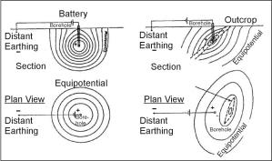
Figure 1. Principle of the mise-a-la-masse method. Right side of figure shows distortion of the equipotential lines due to conductive ore body. (Parasnis, 1973; Copyright permission granted by Elsevier Science)
Example 1 - Buried Ammunition Magazine. Although equipotential surveys have all but been replaced by the mise-a-la-masse variant, there are occasions when passing an electric current directly through the mass under investigation might be ill advised. Such a case is shown in figure 2, in which Heiland (1940) shows the results of a classic equipotential survey over an abandoned ammunition magazine. Distortion of the equipotential lines clearly outlines the magazine, and shows that expensive and/or sophisticated techniques are not always necessary.
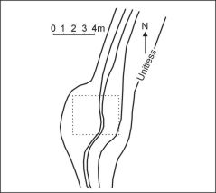
Figure 2. Location of a buried ammunition magazine by equipotential methods. (Heiland 1940)
|
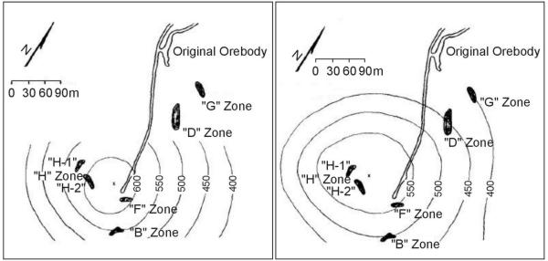
Figure 3. Potential pattern from current source in test position. (Modified from Hallof, 1980) |
Figure 4. Potential pattern from current source in H-1 zone (Modified from Hallof, 1980) |
Example 2 - Advance of Groundwater from an Infiltration Pit. Only one example of mise-a-la-masse used for groundwater investigations was found in the literature. Cahyna, Mazac, and Vendhodova (1990) claim a mise-a-la-masse survey was successfully used to determine the prevailing direction of groundwater leaving an infiltration pit, but unfortunately no figures are included.
Example 3 - Partially Exposed Buried Conductors. The need sometimes arises in hazardous-waste site restoration to trace the extent of buried metal objects such as pipes, cables, and tanks. Often electromagnetic and/or magnetic methods are used to trace these objects, but a special opportunity arises for surveying by mise-a-la-masse when part of the object under investigation has been partially exposed at the surface or in a drill hole. Although no geotechnical examples were found in the literature, one of the numerous mining examples will be used, as the results should be similar. Hallof (1980) shows the results of a mise-a-la-masse survey at York Harbour, Newfoundland, where sulfides were exposed in underground workings. The objective was to find where the ore most closely approached the surface, and if the H‑1 zone and the H-2 zone were the lower portions of a single zone near the surface. Figure 3 shows the equipotential pattern for the near current electrode located at depth but NOT in one of the ore zones. The pattern is nearly circular, and its center is immediately above the current electrode at depth. This was not the case when the current electrode was placed first in the H-1 zone (figure 4) and then in the H-2 zone (not shown). In both cases the center of the surface potential distribution is considerably to the east of the underground position of the mineralization. Further, since almost exactly the same potential distribution was measured for both locations for the current electrode at depth, both zone H-1 and zone H-2 are probably part of a single mineralization that has its most shallow position beneath the center of the surface potential pattern.
The pages found under Surface Methods and Borehole Methods are substantially based on a report produced by the United States Department of Transportation:
Wightman, W. E., Jalinoos, F., Sirles, P., and Hanna, K. (2003). "Application of Geophysical Methods to Highway Related Problems." Federal Highway Administration, Central Federal Lands Highway Division, Lakewood, CO, Publication No. FHWA-IF-04-021, September 2003. http://www.cflhd.gov/resources/agm/![]()