Dielectric Permittivity (ε)
Permittivity is conceptually similar to electrical conductivity. It relates charge separation, rather than current, to the applied electric field. Materials that have no free charge carriers such as ions or electrons may still appear to pass current when a voltage is applied. That is, energy will be drawn from the voltage source to move charge .
The charge that moves is bound to the molecules of the material, for example the positive charge on the nucleus and the negative charges of the electron shells. An applied field polarizes the charge distribution with the positive charges moving in one direction and the negative charges moving in the opposite direction. Figure 1 shows a schematic result of applying an electric field to a molecule.
Intrinsic polarization, p, has units of charge ·distance per meter3, or coulombs/m2. The dielectric permittivity relates polarization to the applied field:
![]() (1)
(1)
The permittivity is often expressed in terms of the permittivity of free space, e0, in terms of the dielectric constant K.
![]() (2)
(2)
As the figure 3 shows, K varies from its free space value of 1 to a maximum of 80 for water. K is strongly frequency dependent in parts of the frequency spectrum, and should more properly be portrayed as complex. For our purposes, these aspects can be ignored. For this report, K is considered only at ground penetrating radar (GPR) frequencies, in the range 100 to 1,000 MHz.
Permittivity is the primary factor influencing the speed of electromagnetic radiation in earth materials at GPR frequencies. Contrasts in velocity, in turn, produce reflections of electromagnetic energy within the Earth. Thus, K is the major influence on ground penetrating radar measurements. From equation 1, e has units of coulombs/(volt-meter) or farads/m. From equation 1, K is dimensionless.
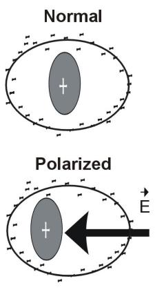
Figure 1. Schematic displacement of charge within a molecule by an electric field E.
The speed V of electromagnetic waves through a medium of permittivity e and magnetic permeability (see next section) m is:
![]() (3)
(3)
The ratio R of the reflected to incident signal amplitude for an EM signal traveling from medium 1 towards medium 2 is:
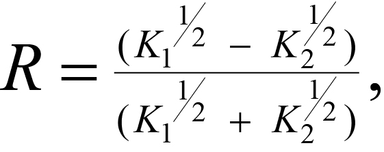 (4)
(4)
With a dielectric constant of 80, water dominates the permittivity of rock water mixtures. There does not appear to be one widely accepted model for water-saturated rocks. One model, proposed by Calvert (1987), is:
![]() (5)
(5)
This relationship is plotted in figure 2.
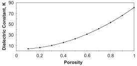
Figure 2. Dielectric constant of a water-saturated rock as a function of porosity (Kw = 81; Km = 3).
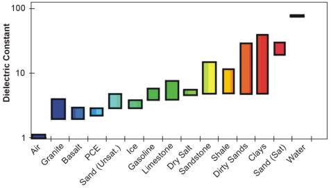
Figure 3. Dielectric constant range for some common materials.
Figrue 3 shows the range of the dielectric constant for different geologic materials including air (dielectric constant = 1) and water (dielectric constant = 80).
Ground Penetrating Radar Attenuation
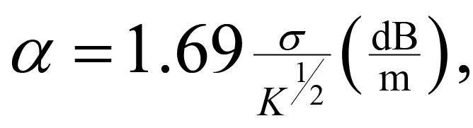
An issue related to conductivity is the attenuation (a) of radar signals by conductive soils and overburden. This is usually quoted in decibels per meter and in the frequency range 100 to 1000 MHz is approximated as (Annan, 1991):
 (1)
(1)
where 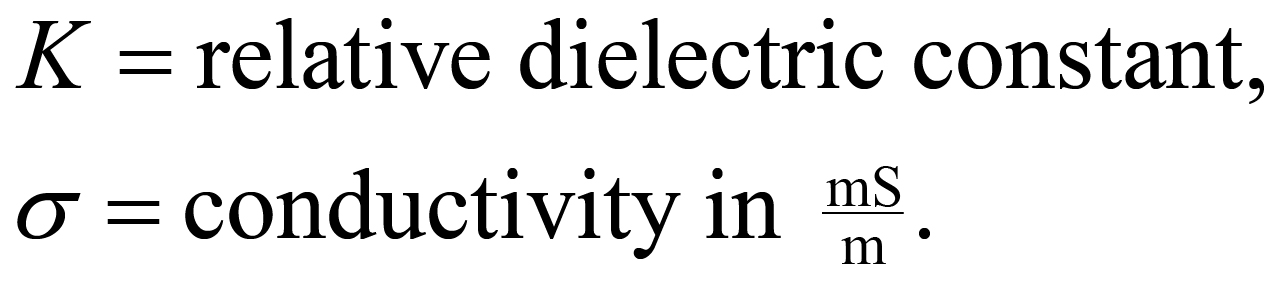
For example, over ground having a conductivity of 30 mS/m and K of 25, a typical GPR signal would be attenuated at a = 10.1 decibels/meter. A good radar system might have 100 dB of sensitivity to use in ground transmission. In this environment, its penetration would be limited to 5 meters (of two-way travel).
The pages found under Properties are substantially based on a report produced by the United States Department of Transportation:
Wightman, W. E., Jalinoos, F., Sirles, P., and Hanna, K. (2003). "Application of Geophysical Methods to Highway Related Problems." Federal Highway Administration, Central Federal Lands Highway Division, Lakewood, CO, Publication No. FHWA-IF-04-021, September 2003. http://www.cflhd.gov/resources/agm/![]()