3D - CT Movies
Since our first publication (Perez et al. 1999), we initially improved our analytical capabilities so that we can make quantitative measurements based on <64% of the total core data and create animations (movies) of 3D images. The details of our methods have been drafted and will be submitted soon for publication. The following brief background is presented in an attempt to facilitate understanding the 3D animations (movies) that can be viewed in this section.
X-rays produce a digitized computer two-dimension (2D) image (tomograph) based on densities within the object (Hendee and Ritenour 1992). These densities are calibrated using a scale of CT numbers (CT#) that relates X-ray linear-attenuation coefficients to pixel brightness on a video monitor or film. Medical scanners are calibrated for air (-1000 CT #), water (0 CT#), and bone (+1000 CT#). Scans of objects containing multiple media generate distributions of CT #s, rather than single values, because objects of different densities influence the CT # reading of adjacent objects. For example, the water that occurs within the tubes and tunnels of macrofauna in sediment will have a CT# range from 0 to ~250 rather than CT# = 0.
Figure 5. Illustrates that the distribution of increasing density
within a sediment core, represented by voxels,
increases with CT#. Therefore, CT#
ranges can be selected to display and quantify specific density features
or "Phases" (gas, water, sediment, rock or shell) within the
sediment as illustrated by the images at the bottom of the figure.
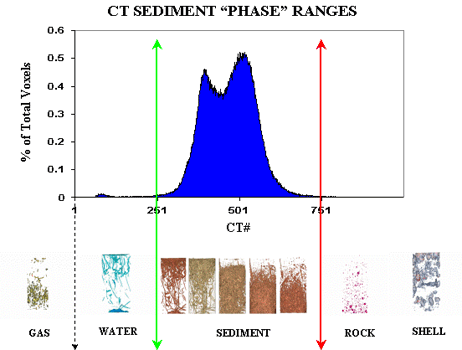
This graph illustrates that CT#s are directly related to the density of objects within sediment cores
The following 3D video clips display the biota and biotic tubes and tunnels within Narragansett Bay sediments. The first three 3D animations are rectangular in shape and represent <64% of the core data because the cores were CT scanned in vertical (upright as collected from the field) orientation. Core scanning orientation is discussed below.
- One living quahog, Mercenaria mercenaria (upper center of core)
- A portion of a large tube, probably constructed by a polychaete worm (at center of core)
- A large tube constructed by the burrowing sea anemone, Ceriatheopsis americanus
- Several small clams
- Numerous polychaete worm tubes
|
Video 2, is of a sediment core taken from a highly polluted site (Fox Point) at the northern end of Narragansett Bay, RI. It shows: |
 |
|
Video 3, is of a sediment core taken at highly bioturbated, pristine area in southern Narragansett Bay. It shows: |
|
The following sequence of 3-D movies further illustrates various core features, which can be visualized by selecting specific CT ranges.
|
Video 4, demonstrates the presence of gas bubbles within a sediment core. Seawater is colored blue and gas is colored yellow. Therefore, gas occurs as both gas bubbles in the sediment coated with seawater (yellow and blue structures toward the bottom of the core) and as air above the air-water interface. |
|
The advantages of CT scanning cores in a horizontal (rotated 90 degrees
from the vertical, lying down and scanned along the axis of uniform circular
cross-sections) rather than a vertical (upright as collected in the field)
orientation are discussed in our recent manuscript (Davey et al. In preparation).
The videos below demonstrate the increased resolution, volume (>90%
of the total core) and cylindrical shape obtained by CT scanning cores
in a horizontal position. The next 3 movies are from the same sediment
core, which was collected from a station within the West Branch of the
Westport Estuary (WBWE), MA., USA. This estuary has limited anthropogenic
point sources, very low nutrient non-point source inputs, and background
levels of sediment contaminants (Johnson et al. In preparation).
|
Video 5, shows the water (CT# range 0 to 250) within macrofaunal tubes and tunnels in a sediment core from the WBWE. |
|
|
Video 6, shows the sediment tubes (CT# range 250 to 400) surrounding the water viewed in Video 5. |
|
|
Video 7, is a magnified view of Video 5 from the sediment-water interface down to a depth of 50mm. The U-shaped structures are amphipod tubes. |
|
|
Video 8, illustrates Crepidula fornicata shells cored from a channel in the Slocum's River Estuary, MA, USA. The sediment from this site was black, hydrated and had a strong odor of hydrogen sulfide. Only the animals at the very surface of the core were alive. |
|
CT Home | Introduction | Methods | 3-D CT Movies | Summary | Glossary | Literature Cited | Contacts
![]()