Photo Gallery - Construction
EPA Demonstrates a Viable and Sustainable Technology
to Treat Wastewater in Central America
US-EPA, Region 4, SESD, Athens, Georgia
[ Report | More Photos and Diagrams ]
|
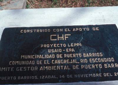
An Inaugural plaque was dedicated at the completion of the project. The plaque includes the names of the main organizations responsible for the project; Environmental Committee of Puerto Barrios, Municipal Government, Corporate Housing Federation (CHF), United States Agency for International Aid (USAID), and the United States Environmental Protection Agency (USEPA).
|
|
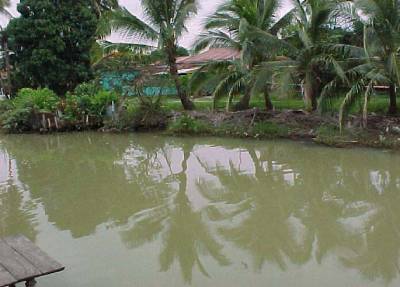
The demonstration wastewater treatment plant (WWTP) would be built along side the Escondido river treating the wastewater discharges emptying into the river.
|
|
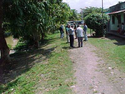
The Puerto Barrios environmental committee in conjunction with US-EPA officials are shown here looking for a public site to build the demonstration site.
|
|
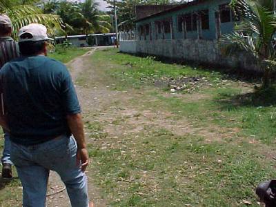
The site that was recommended for the construction of the number two WWTP.
|
|
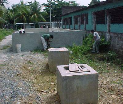
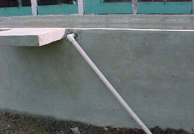
Walls of the recirculating sand filter and the two access ports to the pumping station.
|
|
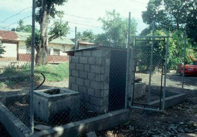
A fenced shelter that was built to control access to the pumping station facility.
|
|
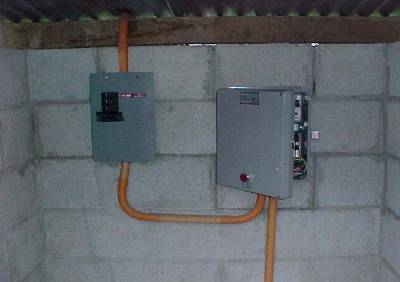
The fuse box and the control box located inside the shelter.
|
|
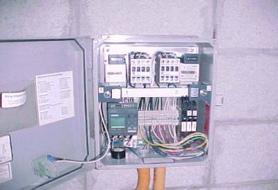
The control box controls the length of pumping cycles in the pump vault.
|
|
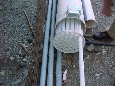
The pump vault supports two pumps and the filter to protect the pumps.
|
|
Floats are used to control the operation of the pumps.
|
|
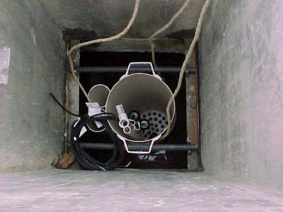
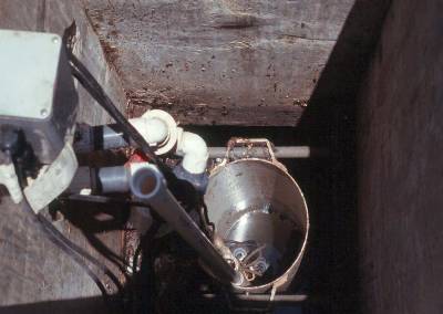
The pump vault is inserted into the pumping tank and placed onto home made support brackets.
|
|
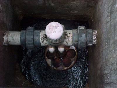
The vault containing the pumps and the electrical box for the wiring from the pumps and the control floats.
|
|
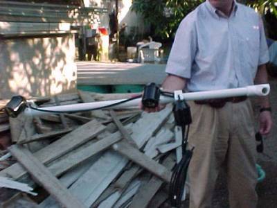
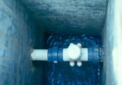
Recirculating valve and float combination.
|
|
With the water level in the pumping tank high, the float plugs the return pipe and a percentage of the treated wastewater discharges to the Escondido river. Some treated wastewater falls back into the tank.
|
|
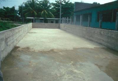
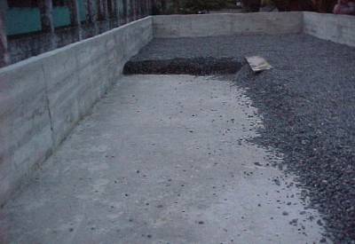
Floor of the recirculating sand filter prior to being filled with the filter media. The floor and the walls are concrete.
|
|
The slotted discharge line for the treated wastewater in the middle of the sand filter.
|
|
The bottom layer of the filter media is composed of gravel.
|
|
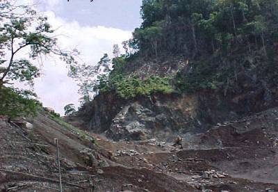
The gravel used as media for the number one WWTP was obtained from a rock quarry mine.
|
|
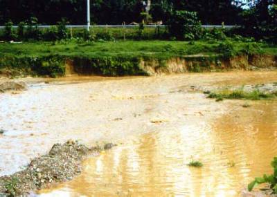
The media used for the number two sand filter was harvested from a river.
|
|
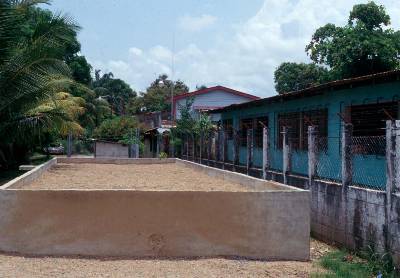
Filter number two view before installation of the distribution system.
|
|
Influent line from the pumping station to the sand filter.
|
|
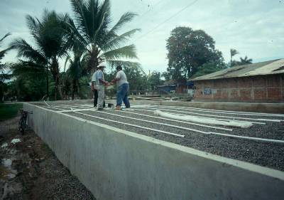
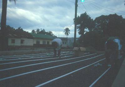
Installation of the distribution lines and the distribution valve.
|
|
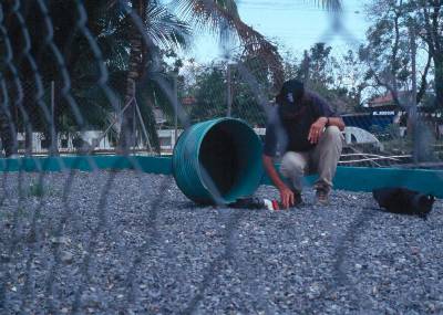
Installing orifice shields along the distribution line on Filter number 1. It is almost dusk after a long day of work.
|
|
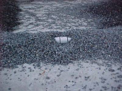
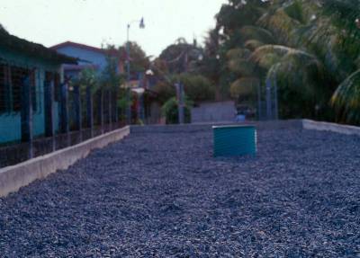
A sand filter with gravel covering the distribution lines. The distribution valve cover can be seen in the middle of the unit. The gravel protects the PVC lines and helps in odor control.
|
|
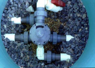
The photo shows an US-EPA Engineer viewing the uncovered distribution valve.
|
|
A closeup view of the distribution valve.
|
[ Report | More Photos and Diagrams ]